
Views: 0 Author: Site Editor Publish Time: 2026-08-31 Origin: Site


Toolrooms, die shops, and prototyping facilities constantly fight the bottleneck between rough stock preparation and final precision machining. You need to execute intricate cuts, internal radii, and complex profiles without eating up expensive CNC milling or Wire EDM hours. A vertical contour saw offers a mechanical, cold-cutting alternative that preserves material integrity. It gives you the flexibility required for unpredictable, one-off tooling and prototype metal parts. This guide breaks down the technical criteria, operational trade-offs, and implementation realities of putting these machines on a professional shop floor. We will look at how to optimize blade selection, manage intricate internal cuts, and balance machine capabilities against facility constraints to improve your overall production efficiency.
Vertical contour saws deliver distinct cold-cutting advantages, preventing heat-affected zones (HAZ) in prototype metal parts and sensitive tool steels.
The viability of specific sawing applications relies heavily on matching versatile vertical band saws with the correct band saw blades, feed rates, and guide configurations.
Built-in blade welding and annealing capabilities are non-negotiable features for die shops requiring frequent internal contouring.
Evaluating these machines requires balancing throat capacity, structural rigidity, and automated feed options against floor space and operator expertise.
Custom fabrication demands rapid material removal with minimal setup. Shops need reliable methods to shape raw stock before committing parts to expensive finishing processes. Defining the success criteria for these initial operations keeps workflow moving and prevents downstream bottlenecks at the CNC stations.
Machining complex shapes directly from solid blocks on a CNC mill consumes valuable spindle time and destroys expensive carbide endmills. Operators reduce this wear by roughing out complex shapes manually or semi-automatically on a contour machine. This approach removes the bulk of the waste material quickly, leaving only a small envelope of material for the CNC machine to finish.
Accelerating the initial stages of die and mold making shortens overall lead times. Toolmakers trace a layout line and cut away large sections of tool steel in minutes. Setting up a similar roughing operation on a mill requires programming, fixturing, and tool selection. The contour machine bypasses these steps, offering immediate material removal for one-off parts like stripper plates, punch retainers, and custom die shoes.
Thermal dynamics dictate how material behaves during secondary operations. Plasma and laser cutting introduce extreme heat into the workpiece, creating a heat-affected zone (HAZ) along the cut edge. The HAZ hardens the material, making subsequent machining operations difficult and unpredictable. Contour sawing is a mechanical cold-cutting process. It generates minimal heat, which operators easily manage with standard mist or flood coolants.
Preserving the metallurgical properties of high-carbon steels, titanium, and aerospace alloys is mandatory during the prototyping phase. A cold-cut edge remains soft and machinable. Toolmakers immediately transition from the saw to a milling machine or lathe without worrying about hardened edges shattering their cutting tools. This metallurgical stability ensures prototype parts perform exactly as engineered during physical testing.
Different operational modes serve specific shop floor requirements. Understanding these modes helps operators maximize the utility of their equipment across various sawing applications.
Navigating tight radii without binding or blade deflection requires specific techniques. Operators feed the material at a steady rate, allowing the teeth to clear the kerf. Forcing the workpiece causes the blade to twist, leading to inaccurate cuts and premature blade failure. Relief cuts are standard practice when approaching sharp corners. These straight cuts remove waste material and give the blade room to pivot.
The relationship between blade width, kerf, and minimum cutting radius is absolute. Operators select the widest possible blade that can still navigate the tightest radius on the workpiece. This ensures maximum beam strength and straightness during the cut.
Minimum Cutting Radius Guide
| Blade Width (Inches) | Minimum Cutting Radius (Inches) | Typical Application |
|---|---|---|
| 1/8 | 3/16 | Intricate scrollwork, tight internal die profiles |
| 1/4 | 5/8 | Standard prototype contouring |
| 3/8 | 1-1/2 | Sweeping curves, medium radius external cuts |
| 1/2 | 2-1/2 | Heavy roughing, large radius contours |
| 3/4 | 5-1/2 | Straight cutoff, massive block shaping |
Internal contouring is a daily requirement in die making. The operational reality involves a strict step-by-step process to ensure the blade tracks perfectly after reassembly. Evaluating the reliability and capacity of integrated resistance welders dictates how efficiently a shop handles internal drop-outs.
Drill a starter hole inside the waste area of the workpiece, ensuring the diameter is slightly larger than the blade width.
Cut the band saw blade using the machine's integrated manual shear.
Thread one end of the blade through the starter hole in the workpiece.
Square both ends of the blade on the built-in grinding wheel to ensure flush contact.
Clamp the blade ends into the jaws of the integrated resistance welder, applying the correct jaw pressure for the blade width.
Press the weld button to fuse the ends together.
Pulse the anneal button until the brittle weld joint turns a dull cherry red, allowing it to cool slowly to restore flexibility.
Grind off the weld flash on both sides and the back edge so the blade passes smoothly through the precision guides.
Operators transition these machines from cutting to finishing using continuous file bands and abrasive belts. File bands consist of short file segments riveted to a flexible steel band. They provide rapid, continuous filing action on internal and external contours, replacing tedious hand filing at the bench. This is highly effective for squaring up internal die openings.
Abrasive belts handle deburring and edge-finishing on prototype parts directly on the saw table. This eliminates secondary hand-finishing operations. Operators swap the standard saw guides for specialized polishing guides with flat backup platens. This versatility allows a single machine to cut a part to shape and immediately finish the edges to a precise layout line.
Contract manufacturing environments leverage programmable stops and automated cut sequences. While contour saws are traditionally manual, modern iterations offer semi-automatic features. Hydraulic tables feed the workpiece at a constant pressure. Operators set travel limits using physical limit switches to stop the cut at precise depths.
This bridges the gap between pure manual operation and full CNC automation for repetitive batch work. Operators set up a fixture, engage the power feed, and step away to perform other tasks. The machine stops automatically once the cut is complete. This reduces operator fatigue and ensures consistent feed rates across multiple parts, extending blade life.
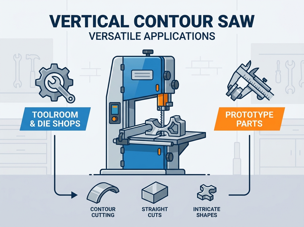
Translating machine specifications into production capabilities requires a clear understanding of mechanical features. Shop managers evaluate several technical dimensions before integrating versatile vertical band saws into their workflow.
Determining the necessary throat depth is the first step in machine selection. Throat depth measures the distance from the blade to the vertical column. A 16-inch throat handles small toolrooms doing localized die repairs and punch modifications. A 36-inch throat handles large contract manufacturers cutting expansive steel plates or oversized prototype panels.
Evaluating under-guide clearance dictates the maximum thickness the machine accepts. High clearance requires exceptional column rigidity to prevent the upper guide arm from deflecting under heavy feed pressures. If the upper arm flexes, the blade wanders off the layout line, ruining the workpiece.
Infinitely variable speed drives transition between diverse metals. Cutting speeds are measured in Feet Per Minute (FPM). High-carbon tool steel requires slow speeds to prevent burning the blade teeth. Aluminum and plastics require high speeds to clear chips effectively.
Direct drive transmissions deliver immediate torque but remain vulnerable to shock loads. Belt-driven transmissions offer a layer of mechanical protection. If a blade jams in the workpiece, the belt slips, preventing damage to the motor or gearbox. Maintenance implications include routine belt tensioning and periodic replacement of worn drive sheaves.
Recommended Cutting Speeds by Material
| Material Type | Speed Range (FPM) | Coolant Requirement |
|---|---|---|
| Tool Steel (D2, A2, O1) | 50 - 100 | Heavy Flood or Mist |
| Mild Steel (1018, A36) | 150 - 250 | Mist or Light Flood |
| Stainless Steel (304, 316) | 40 - 80 | Heavy Flood |
| Aluminum (6061, 7075) | 1,000 - 3,000 | Mist or Dry |
| Plastics / Delrin | 2,000 - 4,000 | Dry |
Heavy-duty cast-iron trunnion systems dampen vibration during heavy cuts. Cast iron absorbs high-frequency vibrations generated by the cutting action. This ensures high-precision contour cutting and leaves a smoother finish on the workpiece edge. Flimsy steel tables chatter, causing premature blade wear and poor part quality.
Two-way table tilt handles compound angle cutting and draft angles in die making. Tables typically tilt 45 degrees to the right and 10 degrees to the left. Draft angles allow formed parts to eject cleanly from stamping dies. The tilt mechanism must lock securely to prevent shifting under the weight of heavy steel blocks.
Evaluating feed mechanisms involves comparing gravity feeds, hydraulic tables, and servo-driven feeds. Gravity feeds use a cable, pulley, and weight system to pull the workpiece into the blade. This provides a simple, low-maintenance solution for consistent feed pressure. Hydraulic tables offer precise control over feed rates and handle much heavier workpieces.
Power feed tables reduce operator fatigue significantly. Pushing a heavy steel block through a blade manually requires immense physical effort and rarely results in a smooth cut. Power feeds maintain a consistent chip load. A steady chip load prevents the blade from rubbing and work-hardening the material.
Tooling dictates machine efficacy. Using the wrong blade material drastically increases consumable replacement frequency and machine downtime. Selecting the right band saw blades remains the most critical operational decision on the shop floor.
Carbon steel blades handle non-ferrous metals, mild steel, and plastics. They cost less but lose their temper quickly if subjected to high heat. Bi-metal blades feature a flexible spring steel back welded to high-speed steel teeth. M42 is the industry standard for tool steels. M51 contains more cobalt, handling work-hardening alloys like stainless steel and Inconel.
Carbide-tipped blades tackle highly abrasive or hardened materials. The carbide teeth resist wear better than any high-speed steel. However, these blades require exceptionally rigid machines. Any vibration or deflection chips the brittle carbide teeth, ruining the blade instantly.
Selecting the correct TPI (Teeth Per Inch) relies on material thickness. Operators follow the rule of three teeth in the cut. At least three teeth must engage the material at all times to prevent stripping. Conversely, too many teeth in the cut cause the gullets to clog with chips, leading to binding and crooked cuts.
Tooth set determines the kerf width and clearance. A raker set features one tooth bent left, one right, and one straight. This handles thick, solid materials and straight-line cutoff. A wavy set features groups of teeth bending gradually left and right. This configuration handles thin materials, tubing, and intricate contouring where the blade needs maximum side clearance.
Precision roller guides and carbide backup blocks prevent blade twist during complex contouring. Roller bearings support the sides of the blade, minimizing friction while keeping the band perfectly vertical. The carbide backup block sits behind the blade, absorbing the thrust force as the workpiece pushes into the teeth.
Manual tensioning mechanisms require the operator to turn a handwheel until a gauge indicates the correct tension. Hydraulic tensioning mechanisms apply consistent, repeatable pressure automatically. Proper tension maintains optimal beam strength. A loose blade wanders off the layout line, while an over-tensioned blade stretches and eventually snaps.
Comparing the vertical contour saw against alternative technologies helps shop managers allocate machine hours effectively. Understanding these trade-offs ensures operators use the right tool for the right phase of production.
Comparison of Machining Methods
| Feature | Vertical Contour Saw | Wire EDM | CNC Milling |
|---|---|---|---|
| Setup Time | Minimal (Minutes) | High (Hours) | Moderate to High |
| Material Removal Rate | High (Roughing) | Very Low | High |
| Thermal Impact | None (Cold Cut) | Micro-HAZ possible | Minimal with coolant |
| Operator Skill Dependency | High (Manual dexterity) | Low (Once programmed) | Moderate |
| Internal Contouring | Requires blade welding | Requires wire threading | Requires pre-drilling/plunging |
The primary trade-off involves manual labor versus programming time. A contour saw relies heavily on operator skill and manual dexterity to follow layout lines accurately. Wire EDM and CNC milling require significant programming and setup time but operate autonomously once started. For a single, complex prototype part, the saw operator often finishes the rough cut before the CNC programmer finishes generating the toolpath.
Optimizing machine hours means using the saw for roughing and the EDM for finishing. Toolmakers saw away 90 percent of the waste material rapidly. They then move the near-net-shape part to the Wire EDM. The EDM only skims the final few thousandths of an inch. This strategy frees up the EDM to process more parts per week.
Calculating ongoing requirements involves tracking blades, cutting fluids, and drive belt replacements. Blades represent the primary consumable. Using the correct feed rates and coolants extends blade life significantly. Cutting fluids require monitoring for concentration and contamination to prevent bacterial growth and rust on the machine table.
Modern variable-frequency drive (VFD) motors offer excellent energy efficiency compared to legacy gearboxes. VFDs draw only the power needed to maintain the set speed under load. Daily use and care routines keep the machine accurate. Operators clean the band wheels to prevent chip buildup. They inspect the rubber wheel tires for wear and lubricate the guide bearings to ensure long-term, dependable performance.
Integrating new machinery introduces operational hurdles. Identifying and solving these common adoption risks ensures a safe and productive shop floor environment.
Improper blade welding, incorrect feed pressure, or bypassed guards create high potential for operator injury or machine damage. A poorly welded blade snaps under tension, creating a severe laceration hazard. Applying too much feed pressure causes the workpiece to slip, pulling the operator's hands toward the teeth.
Implementing strict standard operating procedures (SOPs) mitigates these risks. Shops enforce mandatory use of push blocks for small parts. Blade selection charts hang directly on the machine. Routine welder calibration ensures strong, flexible blade joints. Operators learn to adjust the upper guide arm so it sits no more than 1/4-inch above the workpiece, minimizing exposed blade area.
Inadequate chip evacuation leads to premature guide wear and poor cut quality. Chips carried around the band wheels embed in the rubber tires, causing the blade to track erratically. Cutting cast iron or composites generates fine dust that fouls drive mechanisms and creates respiratory hazards.
Evaluating machines with integrated air blowers, mist lubrication systems, and accessible chip trays solves these issues. An air blower directs a steady stream of air at the cut line, clearing chips so the operator sees the layout line clearly. Mist lubricators apply a microscopic film of oil to the blade, reducing friction without flooding the table with messy liquid coolant.
Vertical contour saws bridge the critical gap between raw stock preparation and precision finishing. They provide immediate, versatile material removal without the heavy programming overhead of CNC equipment. Take the following actions to maximize their utility on your shop floor:
Audit your current roughing bottlenecks to identify where CNC spindle time is wasted on bulk material removal.
Select a machine with a throat depth and under-guide clearance that exceeds your largest typical workpiece dimensions.
Run test cuts on your proprietary materials to verify feed rates, blade compatibility, and coolant requirements.
Establish strict daily maintenance routines focusing on guide alignment, wheel tire inspection, and welder calibration.
A: A horizontal band saw handles straight cutoff operations on long lengths of bar stock or tubing. The blade moves horizontally down through the material. A vertical contour saw features a vertical blade and a flat work table. The operator pushes the workpiece into the blade, allowing for intricate curves, internal cuts, and complex profile shaping.
A: You drill a starter hole in the waste section of the workpiece. Next, cut the band saw blade, thread one end through the drilled hole, and weld the blade back together using the machine's built-in resistance welder. After annealing and grinding the weld smooth, you reinstall the blade and perform the internal cut.
A: Bi-metal blades featuring M42 or M51 high-speed steel teeth handle D2 tool steel best. D2 is highly abrasive and tough. M42 provides excellent wear resistance, while M51 offers additional cobalt for enhanced heat resistance. Carbon steel blades dull almost immediately on D2 and fail quickly.
A: Yes. By adjusting the variable speed drive to a higher Feet Per Minute (FPM) setting and selecting a blade with a coarser tooth pitch, these machines cut aluminum, brass, copper, and plastics efficiently. High speeds clear the larger chips generated by softer materials, preventing the blade gullets from clogging.
A: Blade deflection occurs when forcing the material too quickly, using a blade that is too wide for the target radius, or running improperly adjusted blade guides. Prevent it by using the widest blade that navigates the tightest curve, maintaining steady feed pressure, and setting the side roller guides snugly against the blade.
A: Daily maintenance includes brushing chips off the band wheels and out of the lower wheel housing. Operators check the blade guides for wear and ensure the roller bearings spin freely. The built-in welder jaws require wiping clean to ensure a good electrical ground, and the table tilt mechanism needs clearing of debris.


